Continuous Ventilation Vs Intermittent Ventilation Systems in Houses
This guide describes whole-house mechanical ventilation in existing homes. For an overview of whole-building ventilation systems for new homes, see the Building America Solution Center guide Whole-House Ventilation Strategies for New Homes.
Many older homes are equipped with kitchen and bathroom exhaust fans. While these fans provide intermittent ventilation to remove contaminants near the source, whole-house ventilation is intended to operate continuously (or at automated intervals) to provide dilution of potential contaminants across the whole house.
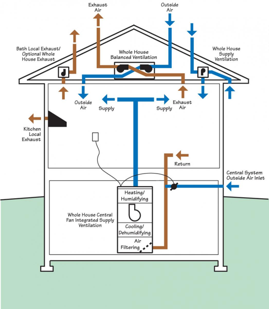
There are three common mechanical ventilation strategies used in residential buildings:
- Exhaust-only - Exhaust-only systems use kitchen, bath, and/or laundry fans to exhaust stale air locally and from the whole house; the exhausted air is replaced by air that is pulled in through leaks in the building envelope or through passive vents. The fans are set to run continuously or intermittently on timered controls.
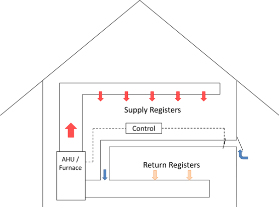
- Supply - Central fan-integrated supply ventilation provides outdoor air through an outdoor air intake that is ducted to the return side of the home's central heating and cooling system air handler for filtering, heating or cooling, and distribution to the house through the HVAC system ducts.
- Balanced - Heat recovery ventilators (HRVs) simultaneously bring in outdoor air and exhaust indoor air, with both ducts passing through a heat exchanger for heat recovery. Energy recovery ventilators (ERVs), function like HRVs but move transfer both heat and moisture. ERVs and HRVs may be connected to the home's central air handler and duct system or independently ducted.
These three strategies are illustrated in Figure 1 and described in greater detail in the section Types of Whole-House Ventilation Systems below. The next section describes factors to consider when selecting a ventilation system.
Further information, including details on calculating ventilation rates, can be found in the Solution Center guide Whole-House Ventilation for New Homes and in the Compliance section of this guide.
Factors to Consider in Selecting a Ventilation System
In assessing a ventilation equipment for existing homes, factors to consider include project goals, program requirements, codes and standards, indoor air quality, humidity control, distribution and mixing of outdoor air, depressurization and other issues with ventilation systems, and energy implications.
Ventilation Goals and Requirements
ASHRAE Standard 62.2 provides minimum requirements for adequate home ventilation. Many codes and programs reference this standard for indoor air quality requirements. Beyond this minimum, additional ventilation and other IAQ-related measures may be needed to account for varying occupancy levels, schedules, activities, health concerns, pets, and other preferences that may influence appropriate ventilation systems and operation. See the Compliance tab for more information on this standard (including changes to versions released in different years) and other codes and standards related to ventilation
All of these ventilation strategies are described in greater detail in the section Types of Whole-House Ventilation Systems below. (See Figure 1 for a depiction of these three strategies.) This guide also includes a short section on humidity control, a topic closely related to ventilation and indoor air quality.
Lawrence Berkeley National Laboratory has compiled an extensive guide to ventilation for new and older homes called Ventilate Right: Ventilation Guide for New and Existing California Homes that provides detailed information on options in ventilation equipment, along with a multistep process for selecting, installing, and commissioning home ventilation equipment.
Codes and Standards Related to Ventilation
(The following is excerpted from the ASHRAE Residential Indoor Air Quality Guide (Schoen et al. 2018).)
The 2012, 2015, and 2018 IRC require whole-house mechanical ventilation for relatively air-tight homes. The ventilation flow rates are similar to those required in ASHRAE 62.2-2010. The codes do not have credits for infiltration as do the ASHRAE standards.
The 2015 IMC, which covers most multifamily dwelling units (those not covered by the IRC, discussed below), requires all occupiable spaces to have natural or mechanical ventilation. It also requires mechanical ventilation in dwelling units with an air infiltration rate of less than 5 ACH50 when tested with a blower door (described in detail in Strategy 1.4). If the jurisdiction also adopts the ICC Code (ICC 2015c) without amendments, a blower door test of 5 ACH50 or less is required, but the IMC does not require it directly. Even if both codes are adopted, this cross-referencing of the two codes can be easily overlooked or neglected, creating an effective loophole. As a result, many multifamily dwellings still rely in whole or in part on operable windows and doors to provide the code-required ventilation. This is not good practice because people do not open windows often enough to meet ventilation requirements.
The IRC (ICC 2015d), which covers detached one- and two-family dwellings and townhouses not more than three stories high with their own entrance from the street, has a section on energy efficiency that requires air leakage of 5 ACH 50 or less in all climate zones (Figure 1.2-A) and specifically requires mechanical ventilation. Increasing numbers of jurisdictions continue to adopt requirements for mechanical ventilation for new dwellings. The latest versions of ASHRAE Standard 62.2 (ASHRAE 2016b) and local codes provide the minimum ventilation rate for a particular dwelling unit.
It can take time for the model codes to adopt rates published in ASHRAE Standard 62.2 and even more time for local jurisdictions to adopt the model codes. Jurisdictions also sometimes edit the model codes before adopting them. Therefore, the ventilation rates in ASHRAE Standard 62.2 are often higher than those required by local codes. ASHRAE recommends that the minimum rates in ASHRAE Standard 62.2 be adopted as a best practice.
Indoor Air Quality
The ASHRAE Residential Indoor Air Quality Guide (Schoen et al. 2018) states that, although building codes and standards have addressed outdoor air ventilation for decades, many dwellings are poorly ventilated, which increases the likelihood of poor indoor air quality (IAQ). The many potential causes of inadequate ventilation include lack of compliance with applicable codes and standards, installation or maintenance problems that prevent delivery of the target ventilation rate, or incorrect use of the installed systems by occupants. ASHRAE Standard 62.2 (ASHRAE 2019) covers the determination of target ventilation rates and fan sizing calculations.
After source control, air changes in a home are the most important factor for decreasing pollution concentrations. In existing homes with natural air change rates above 0.35 ACH, ventilation occurs somewhat naturally through gaps and cracks in the enclosure. In newer homes, with natural air change rates less than 0.35 ACH, additional mechanical ventilation has been shown to help decrease pollutant concentrations of dangerous aldehydes like formaldehyde and acetaldehyde.
Lawrence Berkeley National Laboratory has compiled an extensive guide to ventilation for new and older homes calledVentilate Right: Ventilation Guide for New and Existing California Homes that provides detailed information on options in ventilation equipment, along with a multi-step process for selecting, installing, and commissioning home ventilation equipment.
The ASHRAE IAQ guide also points out issues in addition to ventilation rates that can influence IAQ. These include the following:
- Lack of quality control in the design and installation of heating, air conditioning, and ventilation systems
- Moisture in the enclosure from leaks and humidity
- Poor outdoor air quality
- Moisture and dirt in the ventilation systems
- Indoor contaminant sources such as off gassing cabinetry, carpet adhesives and carpet, cleansers, paints, and finishes.
- Ineffective filtration and air cleaning
- Poor air distribution which can under-ventilate some portions of the dwelling
- Local radon and exhaust.
Other BASC guides provide best practices for addressing many of these issues, such as the guides linked to the EPA Indoor airPLUS checklist.
Indoor air quality sensors for homes are becoming more readily available. These can be stand-alone sensors or they can sometimes be wired to work with controls to activate or increase ventilation rates in the home to address elevated moisture or contaminant levels due to activities in the home such as cooking or showering or increased occupant levels. These sensors can automatically activate ventilation systems or work with home automation systems to alert occupants to activate more ventilation. Sensors can also be used with controls to shut outdoor air intakes if there are unacceptable air quality conditions outside such as elevated humidity, smoke, or particulates in the air.
Installation and Integration with Existing Systems
In existing homes, installing whole-house ventilation systems is often more involved and costly than in new construction—especially with more complicated ventilation systems. The level of effort—and ultimately the cost—required to install a ventilation system in an existing home depends on many factors, including:
- existing ventilation systems
- existing ducted heating and/or cooling
- accessibility to attics and/or basements
- scope of the renovation/rehabilitation project.
One of the most common types of whole-building ventilation is simple exhaust ventilation—where exhaust fans run continuously (or intermittently with a dedicated controller) to remove indoor air. Bathroom exhaust fans can be found in many existing homes, but older fans are usually not appropriate for whole-building ventilation due to poor efficiency, poor air flow, and/or noise. The fan can be replaced with a more efficient model and it may be possible to use the existing duct runs and electrical connections with the new system. Another option is to install an HRV or ERV. HRVs and ERVs individually, or in combination with multiple systems of this type, can provide balanced ventilation.
In homes with existing forced-air heating and/or cooling, it's possible that a new HRV, ERV, or central fan-integrated supply (CFIS) ventilation system can make use of the ducts and the central air handler.
The duct system provides a pathway through which heated or cooled air is distributed from a central air handler throughout the house. However, leaky ducts that run through unconditioned spaces can draw in and distribute contaminants from attics, garages, and crawlspaces. Leaky ducts can also affect pressure differences inside the home that can impact combustions safety and energy efficiency or result in pushing contaminants from one space to another within the home. For these reasons, forced air heating and cooling systems should only be used for ventilation if the ducts do not leak. See our Solution Center guides for more information on duct systems.
When there is no existing duct system—or at least no duct system appropriate for the desired ventilation system—installing new ducts and running electrical service to fans can be invasive and costly. These costs can be minimized if the basement, crawlspace, or attic is easily accessible. If ducts or electrical lines must be run between floors or in existing walls, sections of wall board must generally be removed and replaced. If other aspects of the renovation do not necessitate this level of intrusion, this invasive work can dramatically increase the cost of ventilation installation and integration.
Humidity Control
Achieving AHSRAE 62.2 ventilation requirements in existing homes may increase the moisture content in the indoor space, in humid climates. High indoor humidity can have a negative effect on thermal comfort and can contribute to problems with biological growth. (For more on how ventilation impacts humidity rates, see the report Impact of Residential Mechanical Ventilation on Energy Cost and Humidity Control by Martin 2014.) In many dwellings, simply operating a properly sized air conditioner or heat pump to cool the dwelling is enough to adequately control humidity because dehumidification will also occur when indoor air is cooled with a refrigerant air cooling system. However, the cooling system is set to control temperature, not humidity level.
When the indoor humidity level rises, the system does not necessarily respond by performing more dehumidification unless the dwelling also happens to need cooling. Proper equipment sizing, as described in the Air Conditioning Contractors of America (ACCA) manuals as ACCA Manual S - Residential Equipment Selection and ACCA Manual J - Residential Load Calculation, can improve dehumidification but some dwellings need more dehumidification than the cooling system can provide. These dwellings need a dehumidifier. Dehumidifiers include stand-alone dehumidifiers, which are often installed in sealed basements and crawlspaces; ducted dehumidifiers, which are integrated with a dwelling's air handler; and dehumidifier-ventilators, which can dehumidify outside air brought into the home for ventilation.
Additional dehumidification is often necessary for dwellings in humid climates. Very energy-efficient dwellings and below-grade spaces, which are both likely to use less air conditioning, are more likely to need dehumidifiers. Dehumidifiers can use a substantial amount of energy and not every dwelling needs one. However, when additional dehumidification is necessary, the dehumidification is worth the cost, according to ASHRAE'SResidential Indoor Air Quality Guide: Best Practices for Acquisition, Design, Construction, Maintenance, and Operation (ASHRAE 2018).
Not all excess humidity problems are best solved with a dehumidifier. For existing dwellings or when humidity is excessive in the winter, the first strategy is to identify the source of the humidity and try to reduce or manage it. For example, condensation problems during winter can result from defects in the building enclosure, such as older highly conductive metal window frames or missing insulation. In these situations, eliminating the cold surfaces prevents the condensation. Wintertime condensation problems can also be caused by excessive indoor moisture, which can be addressed in many cases by using bathroom or kitchen exhaust fans.
Dwellings in climates that can have very cold outdoor temperatures can also experience very dry conditions where a humidifier is desired for occupant comfort. However, humidification can threaten IAQ when the system malfunctions, is operated at a higher humidity setting than appropriate, or is allowed to develop biological growth. See the ASHRAE guide, Residential Indoor Air Quality Guide: Best Practices for Acquisition, Design, Construction, Maintenance, and Operation (ASHRAE 2018) for strategies, case studies, and other information on humidity control.
Distribution and Mixing of Outdoor Air
Local exhaust ventilation for source control should be targeted toward areas where contaminants, especially moisture, are frequently generated. Whole-building ventilation is intended to reduce contaminants throughout the entire home by diluting them with outdoor air. Certainly, removing contaminants from and supplying outdoor air to every room in a home is ideal, but the installed costs of such systems can be quite high—especially in retrofit projects. Some ventilation strategies make use of point-source or local ventilation systems to meet whole-building ventilation requirements (e.g., a bath exhaust fan running continuously).
See the reportSelecting Ventilation Systems for Existing Homes for more discussion on the distribution of outdoor air.
Outdoor air brought into a home as part of a ventilation system should be—as much as possible—free from contaminants. See the guide Ventilation Air Inlet Locations for more information on this topic.
Depressurization and Other Issues with Ventilation Systems
Ventilation systems, including exhaust-only systems and improperly balanced ERVs and HRVs, can depressurize a home, pulling more air from the home than is brought into the home. Wind and stack pressure can contribute to house depressurization. Large range hood fans, clothes dryers, and fireplaces also contribute to depressurization of the home if makeup air is not provided.
Depressurization can contribute to indoor air quality issues as follows:
- Depressurizing the home can interfere with any natural-draft combustion appliances located in the home. A home energy rater or HVAC contractor can perform standardized test procedures to assess this issue. Best practice is to remove and replace natural-draft combustion appliances with direct-vent sealed-combustion appliances or noncombustion appliances.
- In a home with an attached garage, depressurization could pull garage air into the home. The wall separating the house from the garage should be completely air sealed and HVAC ducts should not be located in the garage. House pressurization testing can be conducted to confirm the air tightness of the wall between the house and the garage. An exhaust fan can be installed in the garage to exhaust garage air directly to the outside, and to keep the garage at negative pressure with respect to the living space of the home.
- Depressurization of the home has the potential to bring in air and contaminants from basements, crawlspaces, attics, or attached dwelling units if the building envelope is not well sealed; however, if outside air is coming into the home through a leaky building envelope it would likely dilute incoming contaminants. A radon mitigation system should be installed if radon testing shows unacceptable levels of radon. (See the Building America Solution Center guides Radon Fan and Vertical Radon Ventilation Pipe for more information on radon mitigation systems.)
- Supply and balanced systems have been found in field studies to have fouled air inlets and to provide less incoming air than planned. They have often been found to be turned off or closed by home occupants. Maintenance is required to keep the intake grills clean.
- Any existing ventilation system, whether exhaust fans, ERVs, HRVs, or central fan integrated supply systems, should be assessed for effectiveness and any new systems that are installed should be commissioned by a trained HVAC technician or energy rater to verify performance.
Energy Implications
Mechanical ventilation systems have two key energy impacts:
- electricity used to operate fans and ventilation equipment
- thermal energy required to condition outdoor air introduced into the space.
Electrical fan energy varies widely. The power range for most bathroom exhaust fans is 5 to 40 Watts. Power consumption for many HRVs and ERVs ranges from 30 to 200 Watts. The fan in a central air handler or furnace—used in some ventilation strategies—can use 200 to 1,000 Watts. These are very general ranges, and power consumption certainly varies with airflow and system configurations. Typically ventilation products with lower power consumption use variable-speed brushless permanent magnet (BPM) fan motors; these often carry a cost premium.
The second point—conditioning the introduced outdoor air—is climate-dependent. HRVs and ERVs can certainly mitigate this effect. The sensible effectiveness of ERV/HRV heat exchangers typically ranges from 55% to 95%. Again, the higher values typically come with a higher cost. More extreme outdoor temperatures mean greater benefits from heat recovery. In humid climates, the latent heat transfer capability of ERVs can help reduce moisture introduced by a ventilation system. See the Climate tab for examples of the energy and cost implications of various ventilation strategies in different climate zones.
Types of Whole-House Ventilation Systems
Detailed descriptions of ventilation types are provided below for exhaust systems, central fan-integrated supply (CFIS) systems, HRVs, and ERVs.
Exhaust Ventilation
Bathroom exhaust fans have been the standard ventilation practice for decades. Most often the fans are installed in bathroom ceilings with a small duct (typically 4-inch diameter) that carries air to an outdoor termination of some type. While many homes already have exhaust fans, many older fans do not perform at the desired or rated ventilation rates. When local exhaust fans are used for whole-house ventilation, the fans should be set to operate continuously or on programmable timers. Fresh air is pulled into the home through induced infiltration, i.e., cracks in the building envelope or passive inlet vents.
Exhaust Fan Assessment
If a bath exhaust fan already exists, evaluate how well it works as follows.
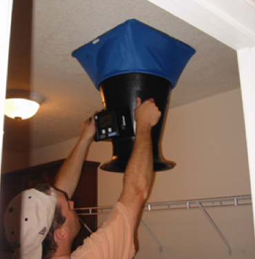
Measure the airflow using a flow hood or other appropriate device, as shown in Figure 2. Inspect the fan grille for dirt and dust. Remove the grille and inspect the fan blades and housing. Simply cleaning the fan housing and grille can sometimes dramatically improve performance. Of course, disconnect power before working on any electrical equipment.
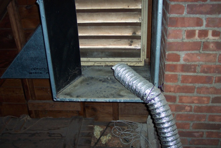
Locate the outdoor terminal of the duct run. Exhaust ducts should always terminate outdoors—never in an attic, basement, or crawlspace, like the exhaust duct shown in Figure 3, which ends near an attic vent grille but not outside. If possible, measure the flow rate at the outdoor termination as well. A large disparity in measured flow rates implies leakage. If possible, trace the exhaust duct run and inspect for disconnects, crimps, leaks, etc.
Even if flow rates are acceptable, many older exhaust fans are not energy efficient nor are they rated for continuous operation. Fan replacement is recommended in most circumstances. Inspect the ceiling cavity for clearances, joist spacing, and mounting configurations. The electrical service to existing fans will often be adequate for newer fans, but as always refer to an electrician or qualified contractor to assess electrical issues.
If a bathroom does not have an existing exhaust fan, evaluate the effort required to install a fan and ducting. If a bathroom is located on the top floor beneath a vented attic, running electrical and ductwork may not be terribly difficult. On lower floors, installing a new duct run may be much more problematic. If the bathroom is on an exterior wall, a fan that exhausts directly through the wall is a possible solution.
Exhaust-Only Cost
Prices for exhaust fans themselves (efficient fans with BPM motors) range from $100 to $250 depending on flow rates, special features, etc. If installed as an upgrade (e.g., in a bathroom that already has an old exhaust fan, power, ducting, etc.), installation costs may be $100 to $200. If installed in a location that did not previously have a fan, costs can be much higher. If installed in a ceiling beneath an accessible attic, installation costs can be about $200 to $400. If drywall or finishes must be removed and repaired, costs can be substantially higher.
Exhaust-Only Energy Implications
A 10-Watt fan running year-round consumes 88 kWh. At $0.11/kWh, this costs $10/yr. As this system has no heat recovery, outdoor air brought into the building must be conditioned. Costs to do this vary with climate and HVAC equipment (see the Climate tab), but these costs are usually much larger than the cost of the electricity to operate the fan.
The pros and cons of the exhaust-only ventilation approach are shown in Table 1.
| Exhaust-Only Pros | Exhaust-Only Cons |
|---|---|
| Low cost for fan equipment and operation | May depressurize home |
| Easy to install – most homes already have one or more exhaust fans and ducting so upgrading to a high-performance model is easy | Point-source, does not draw air evenly from all parts of the home so ventilation and air mixing is not likely to be consistent across the home |
| Easy to test and commission | Intake air is from infiltration through cracks in building envelope rather than from controlled filtered sources |
| Uses very little energy – 5 to 12 Watts for 50 to 80 cfm flow rate | No energy recovery |
| Highly reliable | Homeowner can easily disable |
| Quiet operation | |
| Adjustable flow rate | |
| Can be timer controlled | |
| Require very little maintenance | |
| Some filtration and tempering provided through the building envelope | |
| Works with ductless system |
Selecting Exhaust Fans
Once the desired flow rates are known (based on a calculation to meet code-required ventilation rates, like ASHRAE 62.2), it's usually best to select an exhaust fan that meets these flow rates at pressures of 0.25 inches of water column (in. w.c.). Many fans list flow rates at 0.1 in. w.c., but most exhaust duct runs have much higher pressure drops.
ENERGY STAR-rated exhaust fans are recommended for most applications; the most obvious benefit of these fans is lower energy consumption. ENERGY STAR requirements for bathroom exhaust fans (with rated flow rates below 90 cfm) call for fans to deliver a minimum of 2.8 cfm/Watt. For fans with rated flows of 90 to 200 cfm, ENERGY STAR fans must deliver at least 3.5 cfm/Watt. See the Building America Solution Center guides Continuous Supply/Exhaust Fan Ratings and Intermittent Supply/Exhaust Fan Ratings for information on assessing fan ratings.
While these energy requirements represent great improvements over older fans, many manufacturers now have bathroom exhaust fans with efficacies of more than 10 cfm/Watt. These very efficient fans typically use brushless permanent-magnet motors (BPM motors). These motors are also referred to as DC (direct current) motors, ECMs (electronically commutated motors), or variable-speed motors. In addition to lower energy consumption, the variable-speed capabilities of these motors allow these fans to maintain design flow rates over a wide range of static pressures.
In existing buildings, exhaust duct runs are often concealed in walls or ceilings. It is very difficult to determine the state of these runs, and many have twists and turns that result in higher pressure conditions. Fans with BPM motors and advanced controls are excellent choices for such retrofit applications because these fans can increase speed and flow to overcome most duct restrictions. Operating at higher fan speed increases power consumption somewhat, but this is usually a small price to pay for meeting airflow targets.
One additional benefit of efficient bath exhaust fans is lower noise. ENERGY STAR fans must meet maximum sound level requirements of 2 sones for most products. ASHRAE Standard 62.2-2016 requires a maximum of 1.0 sone when exhaust fans are operated continuously. Many bath exhaust fans are available with rated sound levels of 0.3 sone.
Exhaust Fan Installation
When an older exhaust fan is present, replacing the fan—but keeping the existing duct—can be a relatively low-cost project. If possible, the duct run should be inspected for leaks, insulation, obstructions, etc., and repaired as necessary. Duct size should also be verified; some older ducts may only be 3 inches in diameter; ducts that are too small can restrict flow dramatically. Use the duct size recommended by the fan manufacturer. At a very minimum, the outside terminus of the exhaust run should be located and inspected. Exhaust fans should vent directly outdoors—not to an attic, crawlspace, etc. If an existing fan is terminated inappropriately, a new outdoor termination must be installed. Outdoor terminations should be properly air sealed and flashed and should include proper screens or backdraft dampers to prevent insects and other pests from entering the ducts.
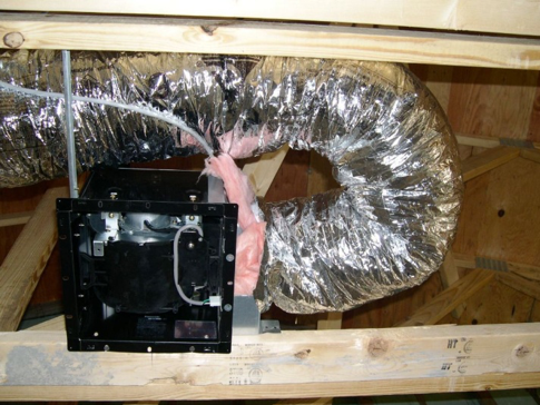
If a new duct must be installed, duct runs should be as short and as straight as possible to an appropriate outdoor termination. If an elbow is required to redirect the ductwork, it is recommended that 2 to 3 feet of straight run is provided directly off of the fan housing prior to the elbow and tight bends, like the bend shown in Figure 4, should be avoided. Refer to fan literature to determine the proper duct diameter; larger ducts generally result in better flow rates and are more forgiving than long or winding duct runs. Joints in the duct system should be sealed with mastic, and any ducts located outside of conditioned space (e.g., the attic) should be insulated to prevent condensation of the humid exhaust air.
Ideally, replacing an existing exhaust fan will require minimal drywall and/or ceiling finishing work. However, the variability in size and configuration of these fans makes this hard to predict. Refer to retrofit installation instructions provided by the manufacturer and, if possible, select a new fan with a ceiling opening similar to—or slightly larger than—that of the existing fan. It's also a good idea to inspect the ceiling cavity to make sure clearances are acceptable. Sealing the fan housing to the ceiling (with caulk or appropriate material) can help maintain envelope integrity.
Exhaust-Only Controls
While simple on/off switch controls may be acceptable in some situations, controls that ensure continuous operation of fans are usually desirable. A wide range of control options are available:
- Timers can operate fans at programmed intervals (usually a set number of minutes each hour). These typically include override switches to turn on exhaust fans when desired.
- Some fans include controls for continuous, low-speed settings along with a switch for a high-speed boost setting.
- Occupancy sensors and humidity sensors can be used to turn on fans or to boost fans into high speed when higher exhaust flow rates are desired.
- There are a wide array of after-market boost switches and timers that work with many exhaust fans.
See the guide Continuously Operating Ventilation and Exhaust Fans for more on fan controls.
Exhaust Measurement, Verification, and Commissioning
Commissioning of exhaust fan operation is usually very straightforward. First, verify that the fan actually turns on when manually switched on and/or when programmed to turn on (e.g., with a timer, occupancy sensor, etc.). The exhaust air flow rate is easily measured with a flow hood or flow meter. If delivered flow rates do not match design rates, inspect the duct system (when possible) to see if there are any obstructions, if backdraft dampers are operating properly, etc. It is common to see the exhaust fan backdraft damper restricted due to screws being used to connect ductwork to the fan housing collar. Screws should not be used to make this connection. Instead, use clamps plus mastic or approved foil-faced tape.
Exhaust-Only Operation and Maintenance
Exhaust fans require relatively little maintenance. To maintain proper flow rates, however, most manufacturers do recommend periodic vacuuming of the exhaust fan grille and cleaning of the fan housing with a damp cloth. Refer to operation instructions for details. On the outside of the home, the exhaust outlet should be checked periodically for obstructions or debris.
Supply Ventilation - Central Fan Integrated Supply (CFIS) Systems
Central fan-integrated supply (CFIS) systems uses a fresh air intake ducted to the home's central furnace or air handler unit to supply fresh air throughout the home. A duct is run between the return plenum and the outdoors (Figure 5). CFIS controllers are programmed to turn on the air handler fan and open the motorized damper. Outdoor air is drawn into the return plenum, mixed with return air, and distributed throughout the home. Supply ventilation can be provided to a home without central air by instead using in-line fans installed in the exterior walls of the home or in an outdoor intake duct that are directed to pull air into the home rather than pushing it out. These homes are electronically controlled to operate in tandem with exhaust fans that have an equivalent amount of air flow to bring air into the home at the same rate is being exhausted elsewhere in the home, those providing some balanced ventilation although is less likely the incoming air will be as evenly distributed throughout the home.
CFIS Assessment
Clearly, CFIS systems are only appropriate in homes with forced-air heating or cooling systems. Examine the air handler and return plenum location. Make sure the area is accessible and that there is adequate room to install an outdoor air duct.
Determine a good air intake location. The air intake should draw in clean outdoor air without restrictions. Outdoor air should not be drawn from an attic, basement, garage, or crawlspace. Intake should be well above the ground and snow level, away from garages or parking areas, and away from any exhaust termination. See the guide Ventilation Air Inlet Locations for more information.
Map the duct run. Make sure a duct can be run from the return plenum to the outdoor air intake location within the project's scope. Duct runs should be as short and as straight as practical to provide unrestricted airflow.
Inspect the AHU fan motor. Determine the type of air handler fan motor and/or measure the power consumption of the motor. Variable-speed motors (also called ECMs or BPM motors) typically use 25% to 50% less electricity than older permanent split-capacitor (PSC) motors when heating and cooling. (See the guide ECM Air Handler Fans for more information.) During fan-only operation, these motors can run at lower speeds and provide further savings. Using CFIS with PSC fan motors is not recommended (and is not permitted by the International Energy Conservation Code, Section R403.6.1).
Determine the outdoor air flow rate and operating schedule. The approximate outdoor air flow rate can be calculated from the measured return static pressure and the total equivalent length (TEL) of the duct run. Each linear foot of outdoor air intake duct counts as 1 foot of TEL, but bends and fittings also increase TEL. Elbows, for example, can add the equivalent of 15 ft to the total length estimate; an air intake hood may add 30 ft. See ACCA Manual D for more details about calculating TEL. See the report Selecting Ventilation Systems for Existing Homes for more details and calculation examples.
The more outdoor air introduced into the system, the less time the air handler must operate to deliver outdoor air. A key limitation, however, is the temperature of the mixed air (i.e., the mixture of return air and outdoor air) supplied to the home. Cool air can cause comfort problems during the winter and many furnace manufacturers require that air passing over the heat exchanger be above a minimum temperature (55° to 60°F is common; see the manufacturer's literature). Locating air intakes upstream from heat exchangers can provide better mixing and dilution of cold outdoor air. The mixed air temperature can be calculated by the ratio of air temperatures and flow rates. See the report Selecting Ventilation Systems for Existing Homes for more information.
CFIS Cost
If the central air handler is accessible in a basement or attic, and a duct can be fairly easily run from outdoors, the total CFIS installed cost may range from $500 to $900 (including the controls, motorized damper, sealed insulated duct run, and outdoor duct termination). If installing the outdoor air duct is involved or requires removal of drywall, refinishing, etc., costs can increase dramatically.
CFIS Energy Implications
CFIS systems can consume large amounts of electricity, because they rely on the HVAC system's large central air handler fan to circulate fresh air for ventilation even when no heating or cooling is called for and the central fan would typically move much more air at a higher power consumption than is really needed for ventilation only. However, variable-speed fans with electronically commutated motor (ECM)can modulate down to a lower flow rate when in ventilation-only mode. If using a relatively efficient air handler unit (AHU) fan motor (300 Watts) and run an average of 8 hr/day for ventilation (i.e., in addition to operation needed for space conditioning), a CFIS would consume 876 kWh/yr. At $0.11/kWh, this costs $96/yr. Most central air handlers have motors that are not this efficient so it is not uncommon for power draws to be two or three times higher.
Basic CFIS systems have no heat recovery, so outdoor air brought into the building must be conditioned. See the Climate tab for examples of these cost implications. If CFIS is used in a system with considerable duct leakage, these thermal conditioning costs can be much higher. However, overall equipment expenses are low since this ventilation method would only be chosen if the home already has a ducted HVAC system with a central air handler or central furnace. The pros and cons of CFIS systems are outlined in Table 2.
| CFIS Pro | CFIS Cons |
|---|---|
| Simple and affordable to install | Home must have a forced-air heating and cooling system |
| Uses existing ducts and blower fan | Higher electricity consumption. Reccomended for central air handlers with ECM blower motors |
| Low maintenance | If duct system is leaky, heating and cooling penalties could be high |
| Outdoor air is drawn from a known location | Could cause comfort issues during very cold or very hot humid conditions |
| Oudtoor air is filtered, at intake and at central air handler | Hard to commission |
| Distribute outdoor air to all parts of home | Low intake air flow rate |
Selecting CFIS Equipment
Controller. There are several CFIS controllers on the market. These controllers are available as discrete components, but many are also available as part of a kit that includes a controller, a motorized damper, and a transformer. Make sure the device (or kit) used is compatible with the existing air handler and control system.
Ducts and Dampers. Duct runs should be as short and straight as is practical. Ducts bringing outdoor air through conditioned spaces should be insulated. Motorized dampers—which open to allow outdoor air in and close when the ventilation quotas have been met—are often available as part of a CFIS package or kit. If a different sized damper is needed, motorized dampers can certainly be acquired separately. Refer to the manufacturer's literature to ensure that the dampers are compatible with the controller. In addition to the motorized damper, a manual balancing damper in the outdoor air duct may help adjust the volume of outdoor air introduced into the system.
Air Handler Fan Motors. As mentioned above, CFIS ventilation systems are not recommended with an inefficient AHU fan motor. For older furnaces or air handlers, there are efficient fan motor replacements available. (See the guide ECM Air Handler Fans.) While the electricity consumption of these motors depends a great deal on HVAC system characteristics, these motors may consume 25% to 50% less electricity to deliver the same flow rate. If central air handlers do not have an efficient motor, and replacing the motor is not possible or practical, a different type of ventilation system is recommended.
CFIS Installation
A qualified HVAC contractor should install the controller, ducts, dampers, and other components. The location of the duct run, connection to the return plenum, and location of the outdoor air intake should be planned beforehand.
Ducts should be sealed with approved foil-faced tape or mastic as appropriate. Ducts running through interior spaces should be insulated to prevent condensation. Outdoor air intakes should be equipped with screens to keep out insects and debris. Outdoor air must also be filtered before entering the air handler; sometimes the AHU filter can be used, but a separate filter is necessary if the outdoor air intake is downstream of this filter. As mentioned above, outdoor air intakes should be well above snow level, but it's preferable that they be accessible from the ground for cleaning and maintenance. Outdoor intakes should be integrated with the siding and flashed properly to prevent air and water intrusion, and penetrations through exterior walls or ceilings should be appropriately sealed to limit infiltration. See the guide Ventilation Air Inlet Locations for more information.
CFIS Measurement, Verification, and Commissioning
After installation, commissioning of the system is critical. The first step is usually checking to ensure that when the controller calls for outdoor air, the air handler turns on and the motorized damper opens. The outdoor air flow rate should then be measured. This can be accomplished in several ways, but two common methods are as follows:
- A measurement in the outdoor air duct with a pitot tube or anemometer will provide air velocity. Velocity (feet per minute) multiplied by the cross-sectional area (square feet) of the duct will yield volume flow rate (cfm).
- At the outdoor air intake, a flow hood can measure airflow being drawn into the system. (This typically requires little or no wind for accurate measurements).
Finally, the balancing damper and the controller should be adjusted so that the desired amount of outdoor air is introduced into the system at the desired schedule.
CFIS Operation and Maintenance
As always, refer to manufacturer instructions for maintenance. One of the appealing features of CFIS systems is low maintenance, but this does not mean "no" maintenance. One very common cause of failure is clogging of the air intake. Regularly check the air intake to make sure it is free from debris (leaves, grass clippings, trash, bird nests, etc.).
Heat Recovery Ventilators (HRVs) and Energy Recovery Ventilators (ERVs)
HRVs and ERVs are balanced systems. This means they exhaust air and supply outdoor air simultaneously at very similar rates. The two airstreams cross in a heat exchanger, where heat from the warm duct is passed to the cooler duct, so during the winter, much of the heat in the exhaust stream is transferred to the supply stream (the reverse is true in the summer). HRVs transfer sensible heat only; ERVs also transfer moisture (latent heat).
HRV/ERV Assessment
Most HRVs and ERVs are housed in rectangular cabinets that contain fans, filters, heat exchange media, etc. Four ducts usually connect to this cabinet: the outdoor air intake, exhaust to the outdoors, outdoor air supply to the home, and exhaust from the home. Use the following steps to assess the viability of an HRV or ERV installation.
- Determine the location for the equipment. The ERV/HRV should be located so that duct runs can be short and straight, power and control wiring can be connected easily, and the unit can be easily accessed for maintenance. Many ERVs/HRVs produce a fair amount of noise; keep this in mind if units will be located near sensitive areas (e.g., bedrooms). In retrofits, basements and attics are common locations for ERVs and HRVs as running ducts from these locations may be less intrusive.
- Determine outdoor air intake and exhaust locations. The outdoor air intake should draw in clean outdoor air. Outdoor air should not be drawn from an attic, basement, garage, or crawlspace. The intake should be well above the ground and snow level, away from garages or parking areas, and far from any exhaust termination. See the guide Ventilation Air Inlet Locations for more information.
- Determine fresh air supply locations. One of the potential advantages of an ERV or HRV system is the ability to distribute fresh air to several locations. While providing outdoor air to all spaces may seem ideal, it is rarely practical. Especially in an existing home, running ducts to all parts of a home is difficult and costly. If an ERV is installed in a basement, for example, delivering fresh air to first-floor spaces may be straightforward but reaching second-floor spaces may be quite challenging. However, even a single fresh air supply register—located relatively far from exhaust registers—can provide better mixing of fresh air than local ventilation systems.
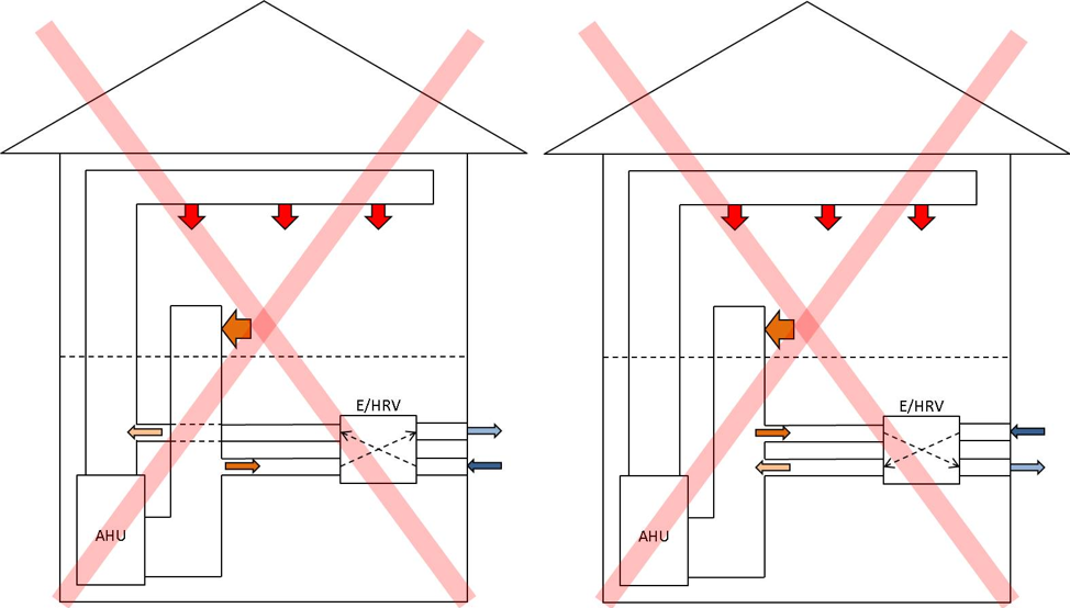
In their product literature, some manufacturers recommend integrating ERVs/HRVs with the central duct systems used for heating and cooling, as shown in the schematics in Figure 6. This requires much less work, especially in an existing home. Short duct runs can bring fresh air to the supply plenum and exhaust can be drawn from the return plenum. Research has found that this strategy does not work well. When the central air handler fan is not running, the outdoor air follows the path of least resistance. In the schematic on the left in Figure 6, the path of least resistance is for fresh air to move backwards through the air handler and be exhausted through the duct in the return plenum. In both arrangements, very little fresh air is introduced into the living space.
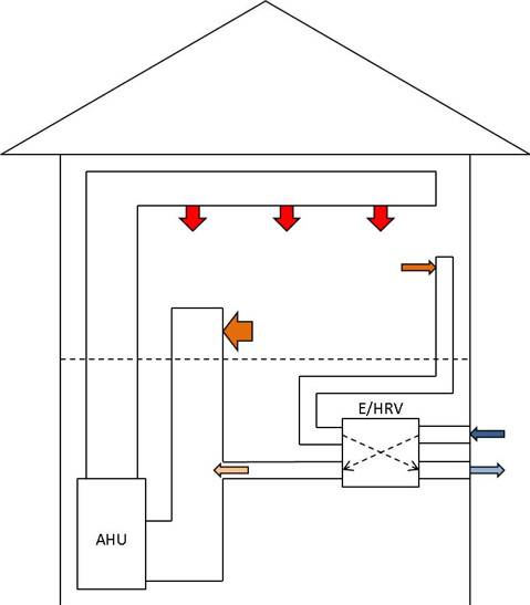
Turning on the air handler when the ERV/HRV operates can solve this short-circuiting problem, but this increases electricity consumption dramatically and is not recommended. In addition, if the duct system is leaky (like most ducts in older homes), this leakage can result in significant energy penalties. One solution is that at least one side of the ERV/HRV system (i.e., either the exhaust or return side) be ducted separately. In Figure 7, for example, air is exhausted through a dedicated exhaust duct and tempered outdoor air is supplied to the return plenum. This can solve the short-circuiting problem but not the duct leakage problem. A fully ducted system—where ventilation supply and exhaust ducts are separate from heating and cooling ducts—may offer the best distribution of outdoor air, but this is often impractical and costly in retrofit applications.
Size ducts and map duct runs. To determine duct sizes, refer to the manufacturer's literature. For more detailed sizing calculations, refer to ACCA Manual D.
HRV/ERV Cost
The range of ERV and HRV equipment costs is quite wide. Until recently, costs for core hardware ranged from approximately $400 to $2,000. Not surprisingly, the units with lower electricity consumption (> 1 cfm/Watt) and higher heat recovery effectiveness tend to be most expensive. Recently, some higher end European products have become available in the U.S. market. These systems boast even lower electrical consumption (near 3 cfm/Watt) and higher heat recovery effectiveness but with price tags of $3,000 to $5,000.
Installation costs vary tremendously; key factors include:
- Location of the core unit. If installed in an accessible space (such as a basement), core equipment installation and duct connections may be fairly simple.
- If ducts can be run in an open space (basement or attic), wall and ceiling finishes may be left mostly undisturbed.
- More and longer duct runs translate into higher installation costs.
- The need for a condensate drain and/or pump adds cost.
Some contractors have quoted installation costs of $1,000 to$1,500 when the system is entirely installed in a basement, attic, or other accessible space (i.e., very little ceiling or wall removal or finish work needed). Rules-of-thumb fail with more complex installations requiring ceiling, wall, or floor removal, construction of chases, refinishing, etc.
To help justify the higher costs of ERVs and HRVs, manufacturers will suggest that one or two bathroom exhaust fans can be eliminated and instead the ERV/HRV can be used to continuously exhaust air from each bathroom. This arrangement often meets code or program requirements for local ventilation, but ERVs/HRVs usually do not deliver the same exhaust rates as dedicated exhaust fans. Also, while this can be a cost savings in new construction, in an existing home that already has exhaust fans installed, the savings are nullified.
HRV/ERV Energy Implications
One of the main benefits of ERVs/HRVs is heat recovery. In colder climates, the savings from heat recovery are more pronounced. The electrical power consumption of these systems can also vary significantly. In milder climates, the electricity costs can actually be greater than the thermal energy savings. See the Climate tab for energy and cost examples. The pros and cons of HRV and ERV ventilation systems are summarized in Table 3.
| HRV/ERV Pros | HRV/ERV Cons |
|---|---|
| Heat and moisture transfer | Higher cost |
| Can distribute ventilation air to many parts of home | More maintenance, regular filter replacement |
| Doesn't include large pressure differences on the buillding. | Energy savings varies |
| Can be a stand-alone system | May be difficult to install and commission |
| Noise |
Selecting Equipmen
Choices need to be made between an ERV and an HRV and equipment thermal recovery efficiency should be considered.
ERV vs HRV
The primary difference between and ERV and an HRV is that ERVs transfer moisture (latent heat) as well as temperature (sensible heat). HRVs transfer sensible heat only; they do not transfer moisture. Which type to choose is not always a straightforward decision, but the key question to ask is: Is it usually too humid outdoors? If so, an ERV may be a better choice.
The ERV/HRV question is easiest to answer in hot, humid climates. In Florida, for example, air inside conditioned homes is generally cool and dry. Outdoor air is quite humid. When outdoor air passes through an ERV, both moisture and heat will pass from the incoming air to the outgoing air, so the incoming air will be somewhat cooled and dehumidified. This does not mean an ERV dehumidifies the home. On the contrary, running an ERV will increase the amount of humidity in the home, but the humidity increase will be less than if a different ventilation strategy was used.
Outside of hot, humid climates, selecting ERVs or HRVs is not as straightforward. Some manufacturers provide recommendations or even maps of the country showing which type of system is most appropriate, but the recommendations vary from manufacturer to manufacturer. A few example situations are below.
- In many older homes in colder climates, indoor air during the winter is often uncomfortably dry—so dry that many people use humidifiers. An ERV can help retain moisture within the home and potentially improve comfort.
- In very airtight homes in cold climates, especially smaller homes with lots of moisture generation, indoor air humidity can be uncomfortably high. In this a case, an HRV can help reduce indoor humidity.
- In hot, dry climates there is a similar trend: larger or leakier homes with low moisture generation may benefit from ERVs (to retain indoor moisture), while smaller, tighter homes with higher occupancy may benefit from HRVs (to reduce indoor humidity levels).
There is not a hard-and-fast rule about which type of system is more appropriate. Especially in mixed climates, there are many situations where an ERV may be more beneficial during the cooling season and an HRV might be more appropriate during the heating season. Installers should use their judgment when selecting systems.
HRV/ERV Thermal Efficiency
The Home Ventilating Institute (HVI) publishes standards for testing and rating the efficiencies of ERVs and HRVs. Apparent Sensible Effectiveness (ASEF) is the most commonly published rating for heat recovery during cold weather. Look for ASEF values above 80%; the most efficient systems have values above 90%. Total Recovery Efficiency (TRE) is listed for ERVs, and it accounts for sensible and latent heat recovery during the cooling season. For best performance, look for TRE values above 50%. A full listing of certified equipment is available on HVI's website.
HRV/ERV Power Consumption. Power consumption can vary widely, from below 30 Watts to above 200 Watts. Systems with low power consumption often have variable-speed motors (ECMs) that allow for better control of ventilation rates. While systems with low power consumption (> 1 cfm/Watt) are often more expensive, they are strongly recommended. In addition to the lower electricity consumption and better controllability, they also usually generate less noise.
HRV/ERV Controls and Features. Most ERVs and HRVs are available with programmable timers of various types. These are usually quite versatile and can be set to various schedules. In many ERVs or HRVs, flow rates can be adjusted by changing the fan speeds. These can often be manually boosted to high speed when more air is desired. Some systems offer advanced features (often at a premium) such as:
- Controls with carbon dioxide and/or humidity sensors can boost speed at higher concentrations (which usually indicate higher occupancy).
- Some systems can boost speed and/or bypass the heat exchanger to take advantage of nighttime cooling.
- Higher levels of filtration are sometimes available (including HEPA) to remove airborne allergens and other pollutants.
HRV/ERV Installation
Installation should be done by a qualified professional. Follow manufacturer instructions for proper installation. Be sure to install the ERV/HRV unit where it can be easily accessed for maintenance, where power can be safely run to the unit, and where the system's noise will not disturb occupants. Install condensate drains as required by the manufacturers.
All duct runs should be as short and straight as is practical. Be sure outdoor penetrations are properly air sealed and flashed and have the appropriate screens for pest protection. Ideally, these penetrations will be easily accessed from the ground so occupants can make sure they stay free of debris.
Ducts should be sealed (see the reportSealing and Insulating Ducts in Existing Homes) and the ducts running to and from the outdoors should be insulated. If the ERV or HRV is installed in unconditioned space (e.g., in a vented attic), the ducts carrying exhaust air and tempered outdoor air should also be insulated.
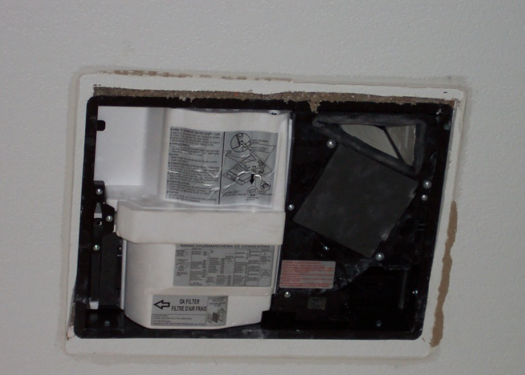
Most of the HRVs and ERVs discussed here are ducted systems—i.e., two ducts run from the unit to the indoors and two ducts run from the unit to the outdoors. The cost for installing these duct systems is often a large part of total system cost. To help address this challenge, some manufacturers have introduced local ERVs. Figure 8 shows such a unit installed in a ceiling in a manner somewhat similar to a bathroom exhaust fan. The unit requires two outdoor air ducts (one intake and one exhaust), but the unit exhausts directly from and supplies directly to the room below. Compared to conventional ERVs, this system can dramatically simplify installation and reduce costs; however, outdoor air is not distributed throughout the home but only to the room or area in which the local ERV is located. Also, heat recovery is only moderately efficient and these systems change to exhaust-only operation in cold weather.
ERV/HRV Measurement, Verification, and Commissioning
As with all ventilation systems, it's important to measure the delivered airflows and make sure they meet specifications or requirements. Measuring flow rates at each register is the only practical way to check system balancing.
If indoor supply or exhaust registers cannot all be accessed (e.g., if air is supplied to the return plenum of the central heating and cooling system), flow hoods can be used at the terminations outdoors. This is usually practical only if the terminations are accessible from the ground and if outdoor conditions are calm (i.e., no wind).
As described for CFIS systems, a duct traverse with a pitot tube or anemometer can provide velocity and flow rate. Some ERV and HRV units are, in fact, equipped with pressure taps so that flows can be measured by connecting a manometer directly to the ERV/HRV itself.
If flow measurements do not match specifications or design targets, adjust the controls if appropriate. If the desired flow rates are hard to achieve, inspect the duct system, registers, and exterior terminations for obstructions. If controls have advanced features (e.g., timers, flow boosts, etc.), ensure that these functions are working properly.
HRV/ERV Operation and Maintenance
As always, refer to manufacturer's instructions for proper maintenance. Maintenance requirements of HRVs and ERVs are often more rigorous than for other ventilation systems. Many systems require periodic cleaning and/or replacement of heat exchange media, filters, and other parts prone to collect dust and dirt. In addition, outdoor air inlets should be checked periodically to make sure they are free from debris (leaves, grass clippings, trash, etc.). Some devices are equipped with indicator lights that alert occupants when it's time for maintenance. If these are not present, residents should be meticulous in maintaining a schedule.
Source: https://basc.pnnl.gov/resource-guides/whole-house-ventilation-strategies-existing-homes
0 Response to "Continuous Ventilation Vs Intermittent Ventilation Systems in Houses"
Post a Comment